By Huan Liao, Kelvin Yuk
This is a brief tutorial on the use of ADS Momentum. For additional information, please refer to:
http://cp.literature.agilent.com/litweb/pdf/ads2008/mom/ads2008/Momentum_Basics.html
Example:
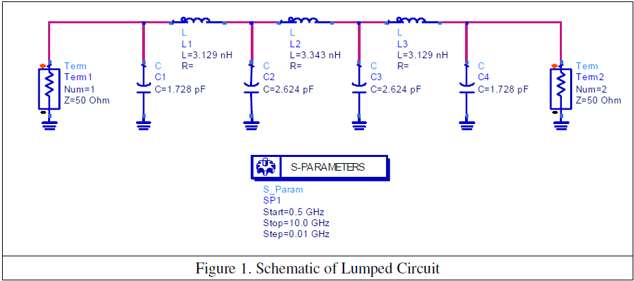
Design a microstrip radial stub low pass filter, with 1 dB corner frequency at 3.2 GHz, and at least 25 dB of attenuation in the range :3.9-6.0 GHz. The lumped circuit design is shown in Figure 1. Simulate this design and plot its S-parameters.
1. Lumped Circuit Design
Figure 1. Schematic of Lumped Circuit
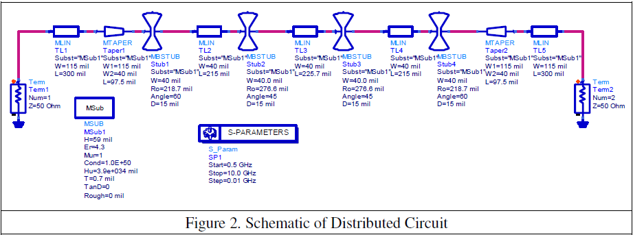
2. Distributed Circuit Design, using radial stubs. The lumped design has been converted into microstrip transmission line elements as shown in Figure 2. Transmission lines have been used in place of the inductors and radial stubs have been used in place of the capacitors. Fifty-ohm microstrip transmission lines and tapers have been added to each end of the filter. Simulate this design and compare it with the lumped design.
Figure 2. Schematic of Distributed Circuit
3. Momentum
1) Generate the schematic for Momentum simulation
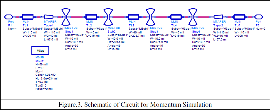
In order to set up the Momentum simulation, a schematic using microstrip components must be converted into a layout and the appropriate ports need to be designed. Using the schematic shown in Figure 2 above, delete the 50-ohm Term components and the S-Parameter block..
Add two ports to the schematic as shown in Figure 3.
Figure.3. Schematic of Circuit for Momentum Simulation
2) Generate/Update Layout
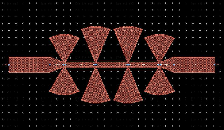
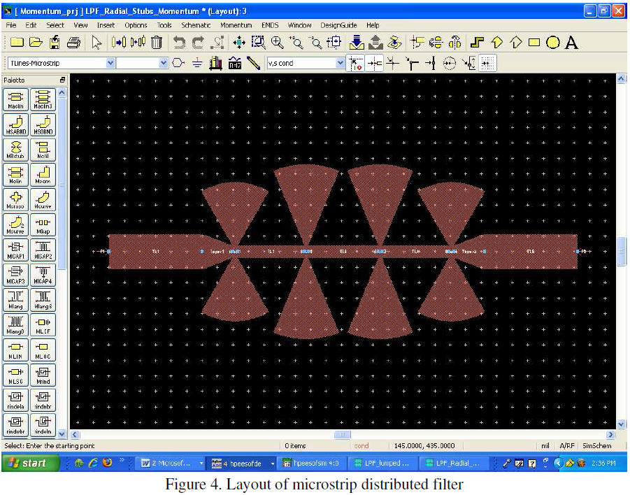
The schematic is ready for conversion into a layout. Go to the Layout menu, select Generate/Update Layout. Click OK in the dialog box. The layout shown in Figure 4. will appear.
Figure 4. Layout of microstrip distributed filter
3) Define and Solve the Substrate
You must instruct Momentum as to how the different metal/slot layers in your drawing are “mapped” to different layers of your substrate.
This is achieved by either (1) updating the substrate parameters defined in the MSUB component (recommended) or (2) by defining the substrate parameters within the Momentum controller.
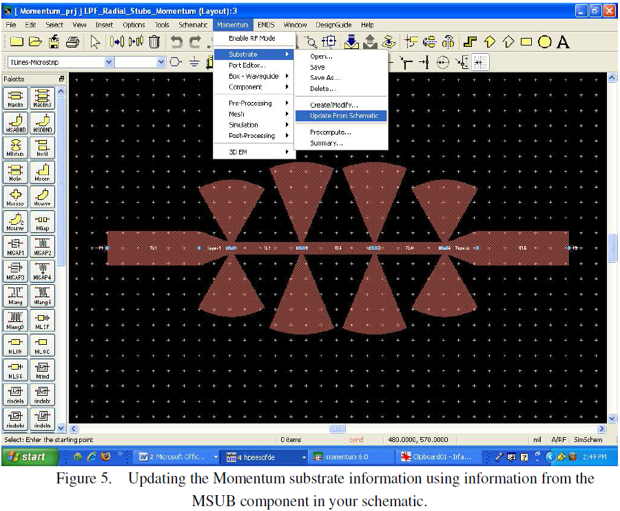
(1) The first is accomplished by selecting Momentum->Substrate->Update from the menu bar in the Layout window as shown in Figure 5.
Figure 5. Updating the Momentum substrate information using information from the MSUB component in your schematic.
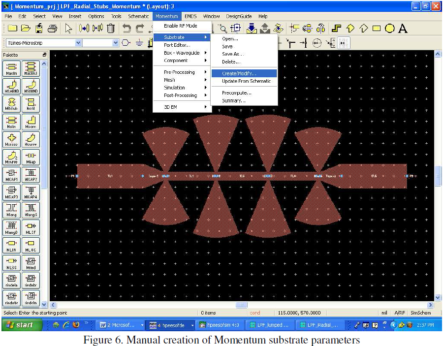
(2) The other requires you to set information about the substrate in an additional dialog box which can be activated by Momentum->Substrate->Create/Modify as shown in Figure 6.
Figure 6. Manual creation of Momentum substrate parameters
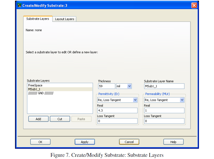
In the Substrate Layers Tab shown in Figure 7, enter the Thickness and the Permittivity which are the same as those in the schematic.
Figure 7. Create/Modify Substrate: Substrate Layers
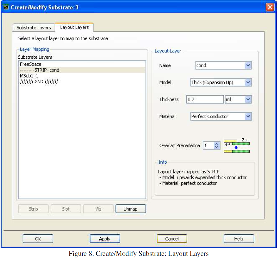
Click the Layout Layers tab as shown in Figure 8. Highlight and enter the Thickness and Conductivity of the metal layer which agree with those in the schematic.
Figure 8. Create/Modify Substrate: Layout Layers
In most cases, you can first perform an “Update from schematic” substrate definition, followed by a check using “Create/modify” option. In this case, the Substrate Layers have been loaded already; you just need to edit the Metallization Layers.
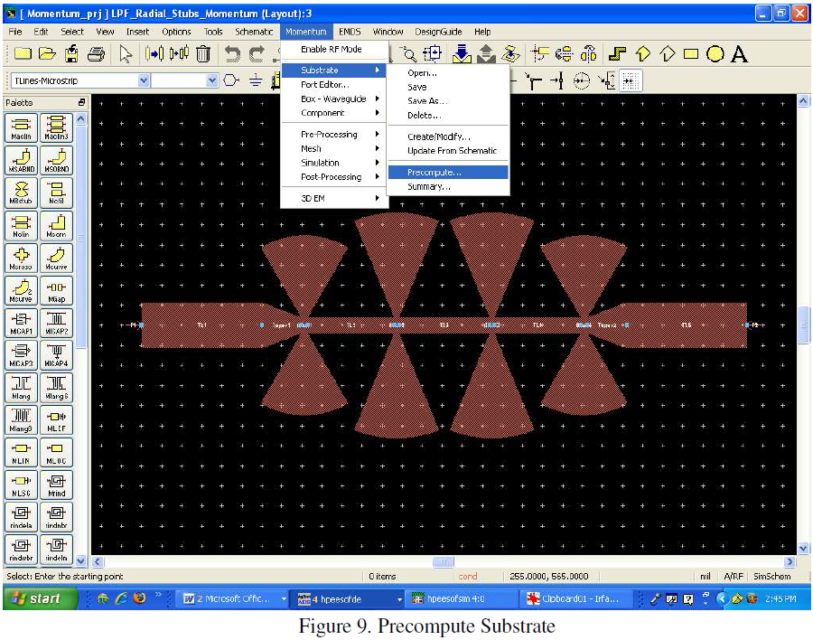
Click on the Momentum pull-down menu and select Substrate -> Precompute Substrate as shown in Figure 9.
Figure 9. Precompute Substrate
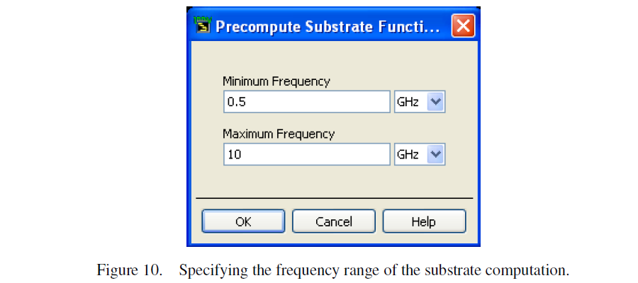
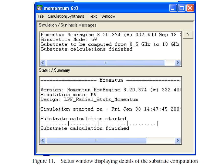
In this step, Momentum will perform a series of computations that are specific to the substrate definition only, not the shapes of the objects in the layout. This is useful since you may be able to use the same substrate for different shapes of microstrip circuits, but you will not have to re-compute these preliminary functions. A pop-up window appear asking for the minimum frequency and maximum frequency of substrate computations. Enter a minimum frequency of 0.5 GHz and a maximum frequency of 10 GHz as shown in Figure 10. A status window displaying details of the computation will appear as shown in Figure 11.
Figure 10. Specifying the frequency range of the substrate computation.
Figure 11. Status window displaying details of the substrate computation
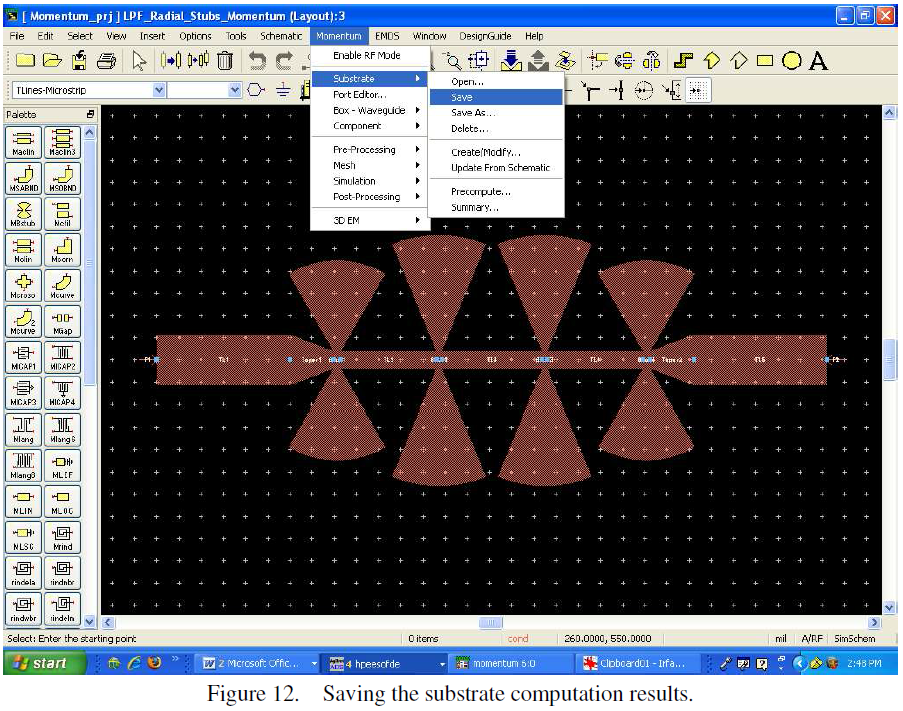
When the substrate calculations are complete, save the substrate computation by clicking on Momentum -> Substrate -> Save as shown in Figure 12.
Figure 12. Saving the substrate computation results.
4) Mesh Setup
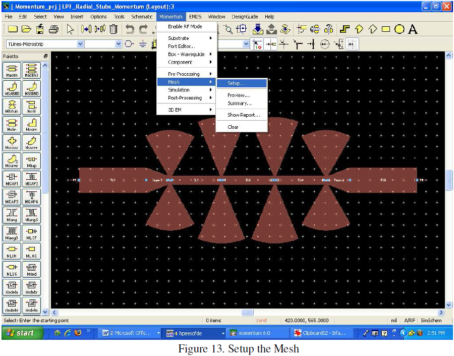
Before the simulation can proceed, we need to define the mesh by opening the mesh setup dialog box. Click Momemtum->Mesh->Setup… as shown in Figure 13.
Figure 13. Setup the Mesh
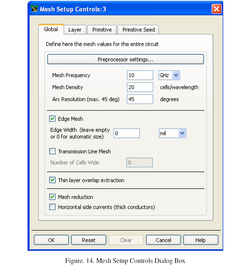
A Mesh Setup Controls window will appear as shown in Figure 14. The important parameter is the mesh frequency which is the highest frequency you want to analyze the circuit for. In our case, 10 GHz will be good. (the higher the frequency, the finer the mesh will be and the longer the simulation time.) Enter 10GHz as the Mesh Frequency and click OK as shown in Figure 14.
Figure. 14. Mesh Setup Controls Dialog Box
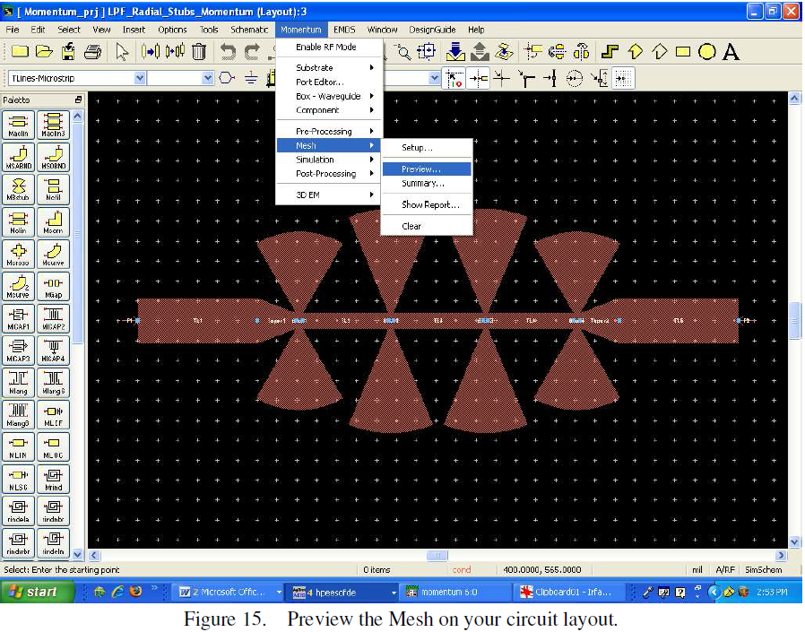
Now preview the mesh on your circuit layout by clicking on Momentum -> Mesh -> Preview… as shown in Figure 15.
Figure 15. Preview the Mesh on your circuit layout.
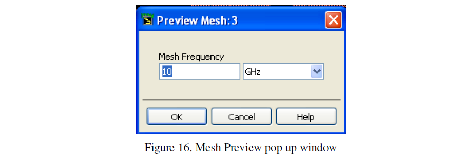
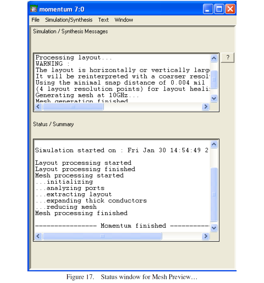
A Preview Mesh window will pop up as shown in Figure 16.. Enter a Mesh Frequency of 10 GHz and click OK. A status window as shown in Figure 17 will appear.
Figure 16. Mesh Preview pop up window
Figure 17. Status window for Mesh Preview…
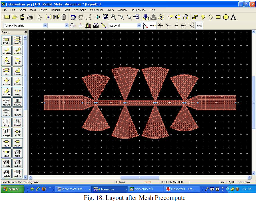
Your layout should now resemble Figure 18.
Fig. 18. Layout after Mesh Precompute
5) Simulation
In this step, Momentum uses the substrate, mesh information and the method of
moments to characterize the circuit.
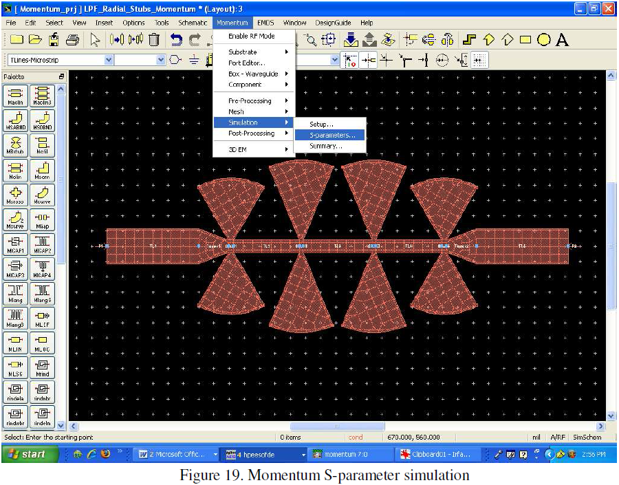
In the layout view, select Momentum->Simulation->S-parameters… as shown in Figure 19.
Figure 19. Momentum S-parameter simulation
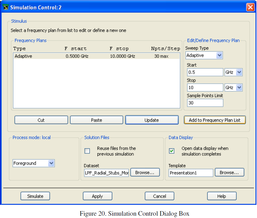
A Simulation Control window will appear as shown in Figure 20. We now have to specify the S-parameter sweep parameters. PLEASE NOTE: DUE TO THE COMPLEXITY OF THIS OPERATION IT IS IMPORTANT THAT YOU CHOOSE “Adaptive” SWEEP AND THAT THE SAMPLE POINTS LIMIT IS SET TO THE MINIMUM THAT IS NECESSARY. THIS OPERATION CAN TAKE UP TO SEVERAL HOURS OR DAYS IF TOO MANY POINTS ARE SPECIFIED.
In the Simulation Control menu, choose the “Adaptive” Sweep Type. Enter a Start of 0.5GHz and Stop of 10GHz. Enter a Sample Points Limit of 30. Then, click “Add to Frequency Plan List” or “Update”.
Figure 20. Simulation Control Dialog Box
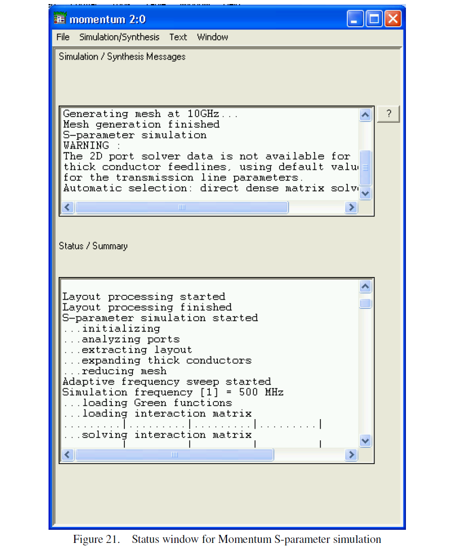
After the frequency sweep plan has been entered. Click the Simulate button to perform a simulation on the layout. PLEASE NOTE: THIS SIMULATION MAY TAKE SEVERAL HOURS TO COMPLETE. A status window as shown in Figure 21 will appear and display the simulation progress.
Figure 21. Status window for Momentum S-parameter simulation
6) Viewing the Results
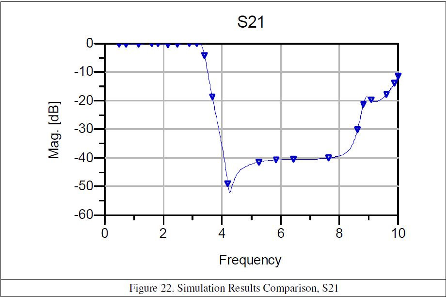
When the simulation is complete, a data display window should open automatically and include separate plots of all four S-parameters. The name of the data set that is created will be the same as the layout filename, with an “_a” extension. This file will automatically be saved to the Data subdirectory of your project as a dataset file (.ds file). The automatically generated plot for S21 is shown in Figure 22.
Figure 22. Simulation Results Comparison, S21
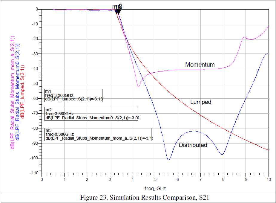
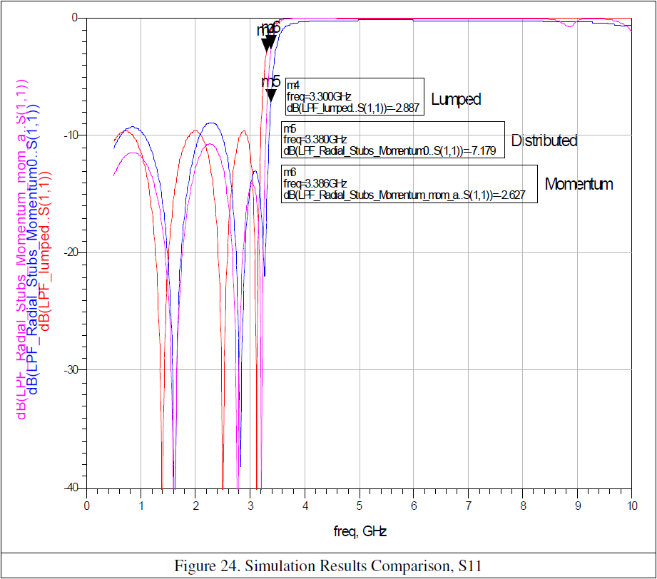
The responses of the Lumped, Distributed and Momentum simulations can be compared on the same plot as shown in Figure 23 and Figure 24.
Figure 23. Simulation Results Comparison, S21
Figure 24. Simulation Results Comparison, S11

